
|
| Man! Once again, like in the mid-nineties, model making has taking over me. The difference is that now I always feel the need to improve what may already be a good model kit. Well the following subject, while being captured splendidly in plastic, could use a little improvement. | ||||||||||
| The Power Loader needs no introduction. I still remember watching Aliens for the first time at age 8. The nightmares that resulted from that! Just when the queen alien had me shaking and I was beginning to think “Awww. Poor Bishop”, this badass, beefed-up fork-lift walks in and begins to pimp slap the hag! |
| I'd seen this kit all over the web for years and about the time I really started to think about trying to acquire my own, I discovered that there was a newer version in the works. Go over to the Forbidden Zone for more info. I figured that I would wait for the new one since it was far bigger than this Halcyon version. Unfortunately though, the release date got pushed back and I just couldn't wait! |
| As far as plastic kits go, this here model was my first venture outside of a familiar town called ERTL, USA (AMT, MPC, RC2... whatever!). I was really happy that Halcyon lived up to its reputation. The kit was well made with quality plastic and no flash at all. The details popped out and there was a healthy amount of parts to play with. Despite all the good things, I still felt that there was plenty of room for modifications. |
| - forks - |
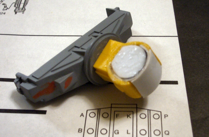
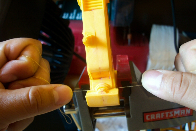
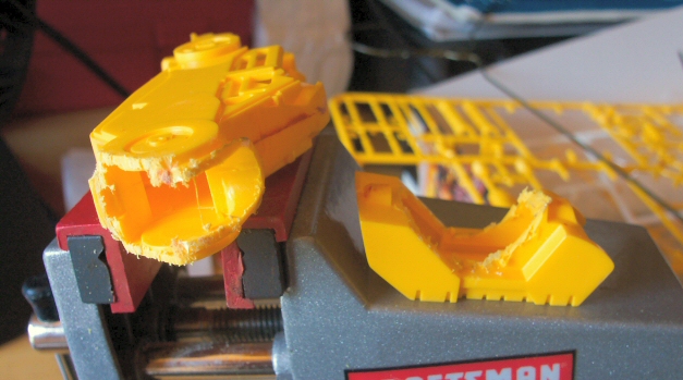
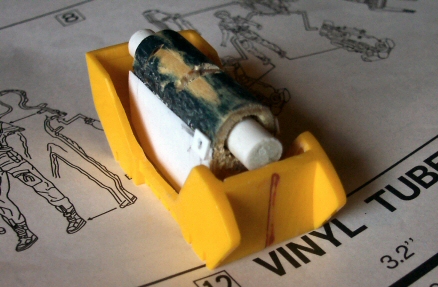
| I began with the pinchers for two reasons, one, because it's my favorite part of the loader, and two, because they were first up in the instructions. I knew early on that I would animate this part of the kit. I began cutting the forks out by first penciling where I would make the cuts, scribing the lines and then using sewing thread to cut through much like a crosscut saw would cut through a tree. I learned this trick way back in my model car days. When done, I added strips of styrene to the areas that were left with open holes. Next, I drilled through the top of the fork holder so that I would have access for the tubing to slide through. I enjoy models with hydraulics because it gives me the chance to add aluminum detail. I then aligned each fork to its respective side and drilled through so that all holes were aligned and even. I'd be lying if I said I didn't have what appeared to be an irreversible mess on my hands but once I saw everything assembled, I knew that I made the right decision. | 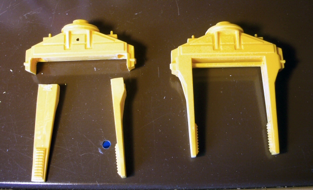 Cutting Out Forks 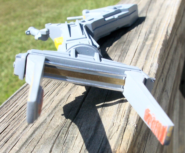 New Working Forks |
| There's a metal bar that runs in between the tubing on the forks. The kit came with this already molded on. Well, it was really thick and inaccurate so I scrapped it. I began thinking of what I could use to replace this with and remembered back in my elementary school days when I would remove that thin metal bar from my wooden rulers and pretend it was a sword. I ran out a bought one and to my amazement, the metal piece was exactly the width I was looking for and is also strong and sturdy! I'll paint this with Alclad II later on. |
| - arms - |
| The arms were started by adding tubing to the "triceps" pistons to add more realism. Any ejector pin marks were filled as well. The forks and pistons were positioned in place when I joined both arm halves and putty was again used for the seams. I'd been thinking of making the elbows and wrists movable joints but since I would have to really manipulate Ripley's arms, I quickly decided not to. However, I changed my mind about the wrists when I planned out the pose. Again, sewing thread was used to cut them out. After this, I built up the missing walls with styrene, super glue and putty. I drilled a straight hole through all the pieces and inserted a piece of wire hanger to allow the wrist to turn. It's also tight enough to hold the fork assembly in any pose. |
    The Process Of Making The "Arms" Movable |
| Although I wasn't going to animate the elbows, I thought it would be appropriate to scribe lines to show where the joints met. I used Dymo tape to keep the lines straight, cut in with a broken tip Exacto and smoothed out with a scriber. Once I saw everything primed I was relieved that I survived this part of the build. The legs, however, will pose an even tougher challenge for me...more on that in a sec. |
| - body - |
| I took a quick break from all the difficult stuff by focusing on the main torso area. Cleanup of all the parts was first as usual. After assembling the body halves, I noticed that the aft tail section (where all the hoses connect) was open underneath. I went ahead and covered that up with some styrene. I'm not sure if this is what this area is supposed to look like but I felt like it was necessary. Most of the small parts that go on the torso would not be assembled until after painting. While experimenting with the pose of the legs, I had to cut the pins that connect the legs to the waist. I then drilled holes into the waist at an angle and inserted custom pins to allow the legs of the loader to be a little more spread out and ready for battle instead of just straight and boring looking. |  Hydraulic Box |
| First times for some things are alright. This build marked my first time working with photo etched parts. I notice detail sets all the time but working with them first-hand, even if only a couple of parts, was really cool! |
| - legs - |
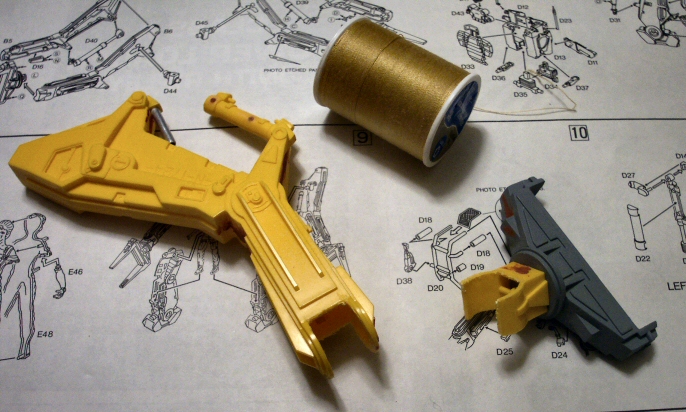
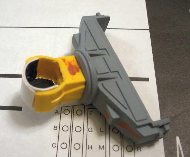
| A little more planning went into this area. The feet would come first. Now, I didn't want the legs to be poseable since it would be fixed to a base but did need to angle the legs a bit. I thought it would be a good idea to borrow Tom Seiler's approach on how he fabricated the 1/8 scale Power Loader. | 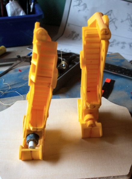 Leg Comparison |
| I used the sewing thread technique to tear the feet out. A whole bunch of plastic was scrapped! I didn't have the correct diameter tubing so I drilled through a perfect sized wooden dowel. I inserted thinner tubing into that. A simple box was constructed underneath this and filled with Durham's Rock Hard Water Putty. Epoxy putty was used to cover the leftover hole at the bottom end of the legs. I only did this so that the armature that would hold the leg to the feet and ankles would be held solid. I re-did this area so many times until I felt it looked ok! I then added aluminum tubing to the "calve" pistons and the smaller ones on the "shin" area. The "shin" pistons had to be made to go with the tilt of the legs, one side being shorter than the other. Finally, styrene was added to complete the round ankle gear. Whew! A couple of headaches went into modifying the legs but I think it was well worth it. Building them straight out of the box meant leaving the whole kit looking very toy-like. |
    The Process of Reposing Power Loader |
| - shoulder joints- |
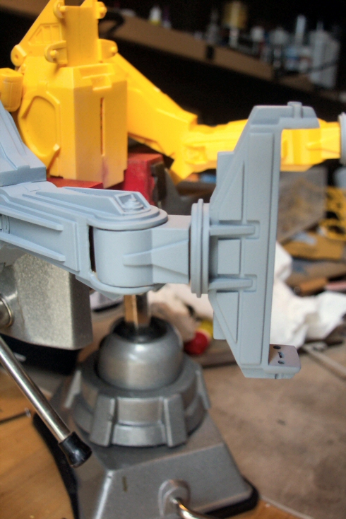
| While planning out the pose, I decided that the right arm would be slung out a little more than what the kit was designed. In order to accomplish this, I used sewing thread, again, to chop these pieces up. I cut a small piece of the appropriate size styrene tubing and sealed off both ends with sheet styrene. I then cut the pin part of the original piece and glued that on to the tubing. An engraving cutter bit for my rotary tool was used to grind out the inside of the piece where the styrene tubing would go in to allow better a fit. | 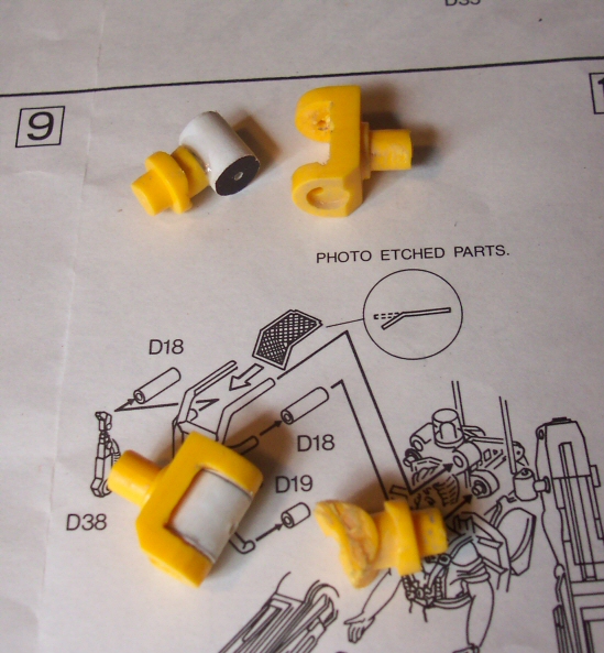 More Movable Joints 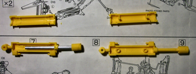 Tubing Detail |
| While I was waiting for the putty to dry on the shoulder pieces, work began on the large rear pistons. As you may know by now, aluminum tubing was a must. Since I would be changing the pose that the kit was designed for, I had to animate these parts. Like I said before, I didn't want to make the kit poseable but modifications like this and the shoulders needed to be done in order to find the pose I was looking for. The mating pins and holes were removed to allow the tubing to slide up and down. |
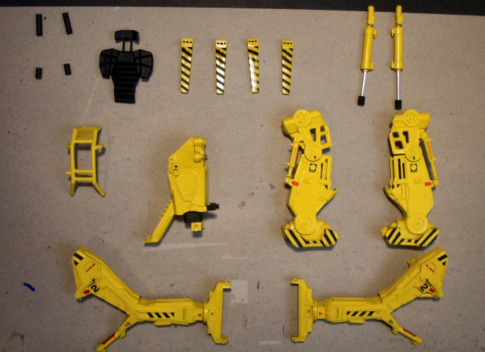
| - painting - |
| I needed to paint the subassemblies first so that I could get to all the nooks. I haven't started on Ripley because I will need to chop up the arms and legs to fit the pose of the Power Loader. She'll be worked on later. |
| I took a quick break from all the difficult stuff by focusing on the main torso area. Cleanup of all the parts was first as usual. After assembling the body halves, I noticed that the aft tail section (where all the hoses connect) was open underneath. I went ahead and covered that up with some styrene. I'm not sure if this is what this area is supposed to look like but I felt like it was necessary. Most of the small parts that go on the torso would not be assembled until after painting. While experimenting with the pose of the legs, I had to cut the pins that connect the legs to the waist. I then drilled holes into the waist at an angle and inserted custom pins to allow the legs of the loader to be a little more spread out and ready for battle instead of just straight and boring looking. | 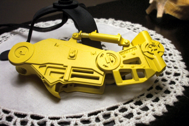 Base Coat |
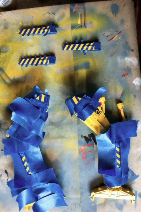 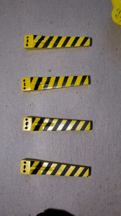  Painting On Warning Lines |
| The decals were next once all the paint was dry. As the Comic Book Guy might say, these are the worst decals ever! First, the protective wax paper was stuck to the decals, ruining most. On top of that, they were very thin and tended to tear easily. I was able to salvage most of the small decals but all of the black lines were trash. It's no biggie since they were inaccurate anyway. I applied what was good and proceeded to mask the feet and arms paying close attention to pics from the movie. This was actually a lot of fun. All was good save a few runs and a torn decal which will be easy to fix. Afterwards, I masked and painted a few areas that needed to be black including the backrest. Weathering will be done next followed by assembly of the loader and then surgery for Ripley. |
| © Copyright 2005-2014. All photos of actual models are property of Joe Jimenez and cannot be used without permission. |