
|
| - missile launcher - |
| This next step was done long after the arms were built. I originally wanted to modify the rocket launcher area but didn't feel too confident for some reason. Again, Ken Rice's work on his ED-209's rocket launcher inspired me to gather the courage and do it. I was very happy with the result! |  Cutting Out Tubes 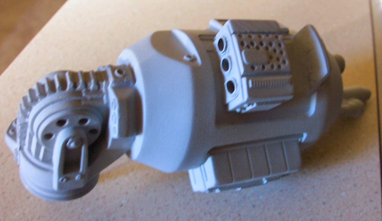 Rebuilt Inner Walls |
| I cutout the sorry excuse for launch tubes and cleaned up the dry foam that was already there from prior filling. I then built up the missing walls with sheet styrene and filled the seams with putty. The outer tubes were scratch-built from soft copper tubing and the rest of the tube that runs through the launcher were pieces of regular aluminum tubing. The missiles are made from wooden dowels sharpened in an electric sharpener and filed down to a blunt tip. |
| - Rails - |
| The rails were closed off and looked horrible. I heated up the plastic and carefully cut out the excess. I also cut a tab of plastic out on each rail, front and back, to match the reference I was looking at. | 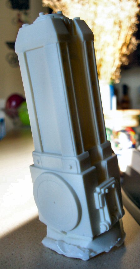 OOB Rails 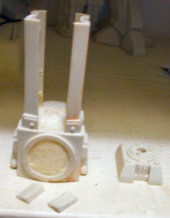 Chopped Up Rail  Coming Together 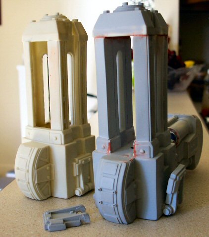 Final Result |
| I filled only the lower block area of the rail piece with foam. This way, the bottom missing wall I would build would have something to rest on while gluing. The hole in the center was pre-drilled prior to assembling, centering it as best as I could. Pieces of For Sale signs were used to build up the inner rails. And since the signs were fairly thin (.020 or so),, I had to build the walls up in two layers to keep everything flush. I was having a hard time working in the tight space so after much debate I trimmed off the top (or cap) piece that sits on top of the rails. | |
| I decided to cut out the locking flaps on the side of the rail piece as well. There was no reason I did this other than curiosity of whether I could or not. I added styrene on the back and plan on rigging them to move like the shoulder pads. | |
| Now, I was able to finish off the inner rails with greater ease and followed by filling the gaps with putty. I filled the cap with foam as well as the space in between the kit rails and the walls I had built. Holes were drilled into each corner of the cap and nails (to act as alignment pins) glued into place. I had also drilled a hole through the cap so that I could insert a threaded rod to simulate the screw looking guide that the rails run on. After all that, I went through filling in seams with putty. I didn't completely fill in the seam between the rail and top cap since there should be a separating line there anyway. |
| - hip - |
| This was very simple. I filled the hip and two hip connector pieces separately with foam. I then glued all pieces together. I didn't bother with joint supports here since I would later run one long wooden dowel through the hip piece connecting everything between both upper leg ("thigh") pieces. | 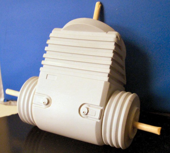 Hip Piece |
| - Upper leg (thigh) - |
| Up next were the thigh pieces. I had already filled the piece with foam when I decided that I wasn't happy with the hydraulic actuators. Here was another point where I was a bit hesitant to go through with scratch building. |  OOB Rails 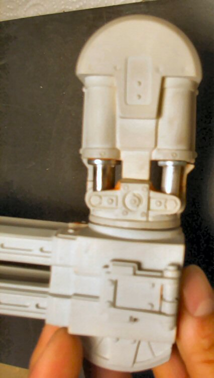 Patching It Up 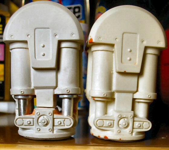 Comparison Another Comparison Prepare For Paint |
| Well, as you can see I decided to go ahead and do it! I chose to go with aluminum tubing for the steel actuator stems because of the natural color. Back when I was scratching the missile launcher, I discovered that I really didn't like the result of using my rotary tool to cut tubing. It usually left jagged edges. I decided to invest in a mini-tubing cutter which was worth the $3.50 I spent on it. Also, somewhere around this time, the tight space issue arose and since I had success with trimming off the caps from the rail piece, I decided to chop this piece up to reach the nooks. After warming the piece and cutting out the plastic rams and underlying foam, I cut the piece at certain locations. The missing walls were built up with styrene. Holes were then drilled into the bottoms of the hydraulic cylinders so the stems could be epoxied into them. | |
| When the time came to re-attach the chopped piece, I inserted and epoxied a wooden dowel into the larger half. Keep in mind the dowel was measured so a length of it sticks out the bottom where it will go into the rail piece for joint support later on. For better alignment and support of the thin plastic pieces that run down the middle of the actuators in front and back, I took thumbtacks and cut off the pins. I then drilled tiny holes into the mating areas, super glued the pins into one piece and when dry, inserted the other end into the hole of the other piece, creating my own alignment pins. The wooden dowel and tape held the two pieces together very tight while the epoxy dried. | |
| When dry, I went back and filled all noticeable seams and areas that I had over trimmed. The final result blew me away! Compare the modified piece with the kit version. | |
| Next, I masked the hydraulic stems, aligned the rail and thigh pieces and epoxied together, letting it dry over night. |
| © Copyright 2005-2014. All photos of actual models are property of Joe Jimenez and cannot be used without permission. |